Arduino IDE 1.0.1からの新機能でpinMode関数の第2引数にINPUT_PULLUPキーワードが使えるようになっています。この機能、便利なんですけどあまり知られていないのかもと思い、改めてご紹介いたします。
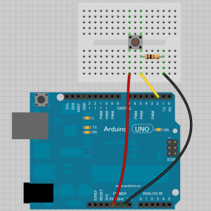
Arduino IDE のメニューから「ファイル」→「スケッチの例」→「02.Digital」→「Button」をクリックすると、タクトスイッチや押しボタンスイッチを押している間、LEDが光るスケッチが開かれます。本当に基本的なボタンの使い方ですね。スケッチの先頭に配線方法が書かれています。
/*
  Button

 Turns on and off a light emitting diode(LED) connected to digital
 pin 13, when pressing a pushbutton attached to pin 2.

 The circuit:
 * LED attached from pin 13 to ground
 * pushbutton attached to pin 2 from +5V
 * 10K resistor attached to pin 2 from ground

 * Note: on most Arduinos there is already an LED on the board
 attached to pin 13.

 created 2005
 by DojoDave <http://www.0j0.org>
 modified 30 Aug 2011
 by Tom Igoe

 This example code is in the public domain.

 http://www.arduino.cc/en/Tutorial/Button
 */

// constants won't change. They're used here to
// set pin numbers:
const int buttonPin = 2;     // the number of the pushbutton pin
const int ledPin =  13;      // the number of the LED pin

// variables will change:
int buttonState = 0;         // variable for reading the pushbutton status

void setup() {
  // initialize the LED pin as an output:
  pinMode(ledPin, OUTPUT);
  // initialize the pushbutton pin as an input:
  pinMode(buttonPin, INPUT);
}

void loop(){
  // read the state of the pushbutton value:
  buttonState = digitalRead(buttonPin);

  // check if the pushbutton is pressed.
  // if it is, the buttonState is HIGH:
  if (buttonState == HIGH) {
    // turn LED on:
    digitalWrite(ledPin, HIGH);
  }
  else {
    // turn LED off:
    digitalWrite(ledPin, LOW);
  }
}
この通りに配線すると下図の様になります。
LEDは、Arduino Uno上のモノを使うことにして配線を省略しています。
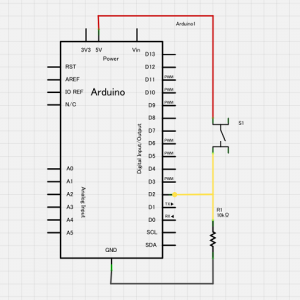
回路図にすると
こんな感じですね。ボタン読み取りピンは、ボタンが押されていない時にGNDに繋がるようにプルダウン抵抗が入っています。 この時にボタンピンを読み取るとLOWになりますね。ボタンが押された時には+5Vに繋がり、読み取るとHIGHになる仕組みです。
このスケッチではボタン読み取りピンの設定でpinMode(buttonPin, INPUT); とINPUTキーワードを使っています。
ここで、このINPUTキーワードの代わりにINPUT_PULLUPキーワードを使ってみましょう。このキーワードを使うと、そのピンがINPUTモードになると共に、マイコンチップ内部のプルアップ抵抗が有効になります。先ほどの回路ではプルダウン側に抵抗が入っていたのですが、逆のプルアップが有効になるので、ボタンを押していない時と押した時の関係が逆になるように配線(回路)とスケッチを直さなければなりません。
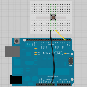
配線は
先ほどのと比べると、抵抗とジャンパワイヤが1本減ってずいぶんシンプルになりましたね。
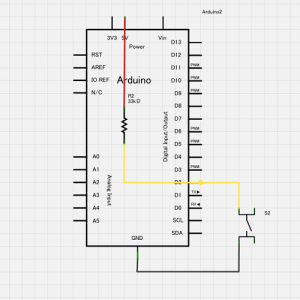
回路図は
こうなります。普通の回路図では書かれない内部のプルアップ抵抗も比較のため表してみました。抵抗値はデータシート上最小20KΩ~最大50KΩ程度の様なので、間をとって33KΩの表示をしました。
さて、このように回路を組み、読み取りボタンの設定を pinMode(buttonPin, INPUT_PULLUP); と変更します。すると、ボタンが押されていない時にボタンピンを読み取るとHIGHになり、ボタンが押された時にはLOWになります。最初とは逆の値で読み取られるため、読み取った値を使う部分も変更しなければいけません。
if (buttonState == HIGH) { この判定を逆の if (buttonState == LOW) { に変えましょう。
const int buttonPin = 2;
const int ledPin =  13;
int buttonState = 0;

void setup() {
  pinMode(ledPin, OUTPUT);
  pinMode(buttonPin, INPUT_PULLUP); // Inputモードでプルアップ抵抗を有効に
}

void loop(){
  buttonState = digitalRead(buttonPin);
  if (buttonState == LOW) {     // ボタンが押されていたら、ピンの値はLOW
    digitalWrite(ledPin, HIGH);
  }
  else {
    digitalWrite(ledPin, LOW);
  }
}
これで、元のスケッチ・回路と同じ動作になりましたが、ボタンの状態がどうなった時の処理なのか、分かりにくいですね。そこで、buttonON,buttonOFFという定数を用意してこれと比べる様に直してみます。
const int buttonON = LOW;    // ボタンが押されているとピンの値はLOW
const int buttonOFF = HIGH;  // ボタンが押されていないとピンの値はHIGH

const int buttonPin = 2;
const int ledPin =  13;
int buttonState = 0;

void setup() {
  pinMode(ledPin, OUTPUT);
  pinMode(buttonPin, INPUT_PULLUP);
}

void loop(){
  buttonState = digitalRead(buttonPin);
  if (buttonState == buttonON) {     // ボタンが押されていたら
    digitalWrite(ledPin, HIGH);
  }
  else {
    digitalWrite(ledPin, LOW);
  }
}
これで、分かりやすくなったでしょうか。
今回はArduinoのAVRマイコンチップが持つ内部プルアップ抵抗の機能をINPUT_PULLUPキーワードで使ってみました。 これを知っていれば、配線やパーツを減らすことが出来ますので、ぜひご活用下さい。


